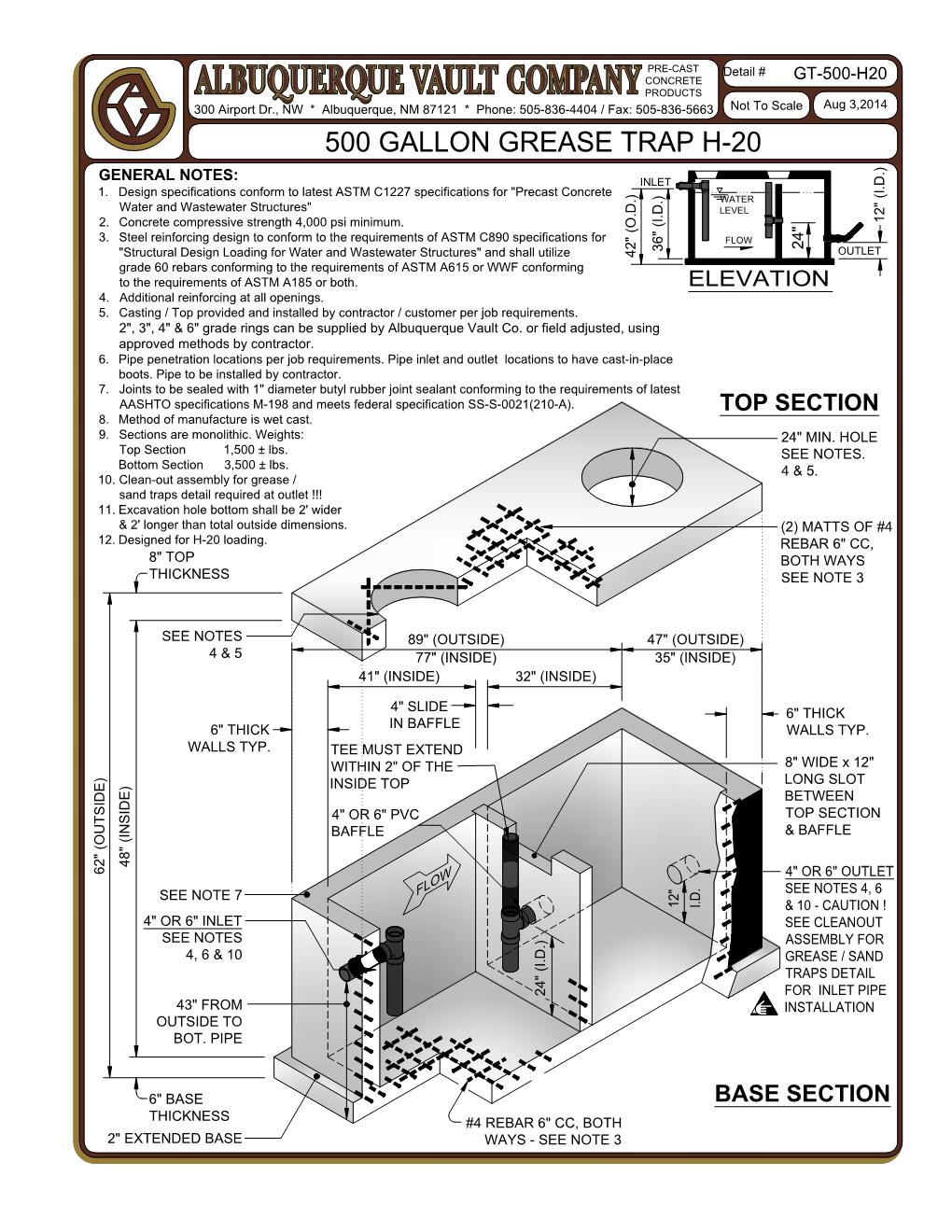
Grease Trap Design Drawings
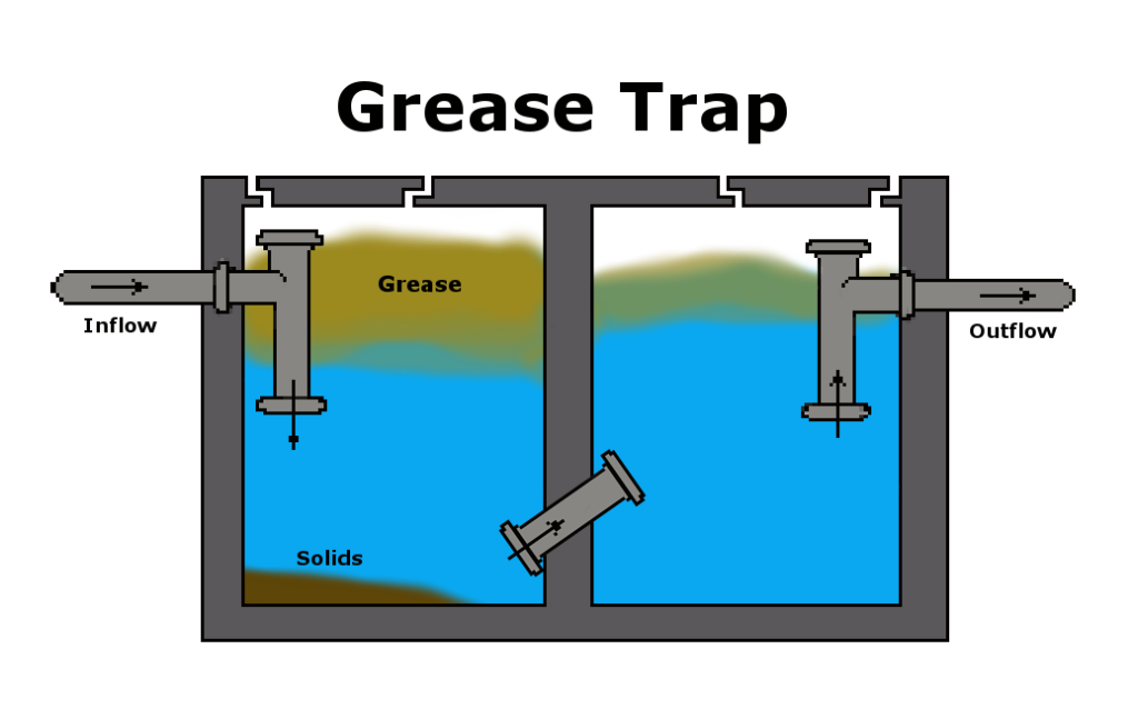
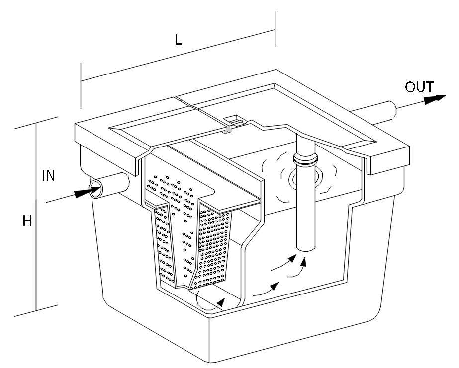
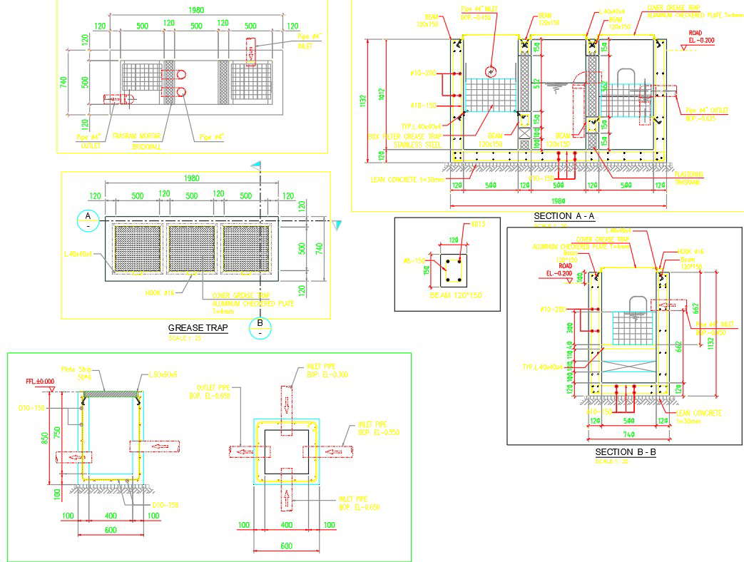
Grease Trap Design Drawings - Web in this blog post, we will discuss the importance of grease trap design, its key components, and the benefits of professional grease trap drawings. Web design drawings serve as a crucial tool for communicating and visualizing the specifics of your grease trap system. Web one of the most reliable ways to manage fog and prevent an sso from occurring is to use a precast concrete gravity grease interceptor. Contains development in section, plant and accessories and specifications for use and construction. The type and/or size of your business will determine the appropriate size of your grease trap. Web grease trap definition • a tank or series of tanks into which wastewater that contains grease is discharged, where grease floats to the water’s surface and is retained while water below is discharged. Web displaying grease trap design drawing.pdf. 50 gpm grease trap cad drawings zip file. Constructive development of a grease trap design. By downloading and using any arcat cad drawing content you agree to the following license agreement. Web susan gresh, owner of biotech drainline services, explained that restaurants and commercial establishments have these traps to prevent clogged or damaged pipes. We will also highlight some common mistakes to avoid during the design phase to help you achieve an efficient and effective grease trap system. Web displaying grease trap design drawing.pdf. 50 gpm grease trap cad drawings zip file. Web download cad block in dwg. Contains development in section, plant and accessories and specifications for use and construction. Web autocad dwg format drawing of a grease trap chamber detail, plan, front, and side elevation 2d views for free download, dwg block for sanitary installation details. The type and/or size of your business will determine the appropriate size of your grease trap. 1.01 installation of a grease trap / interceptor is required at all commercial, institutional, and industrial facilities that contain businesses, classes, or occupations that generate fats, oils, and grease (hereafter referred to as fog), grit, silt, or clay. Web grease traps cad drawings. Web use the grease trap sizing calculator to determine the flow rate for each individual sink that will be serviced by the trap. 50 gpm grease trap cad drawings zip file. Web design drawings serve as a crucial tool for communicating and visualizing the specifics of your grease trap system. Web grease traps are designed to hold wastewater for a. Web browse and download thousands of cad files. Free grease traps architectural cad drawings and blocks for download in dwg or pdf formats for use with autocad and other 2d and 3d design software. The minimum size for a grease trap is 1,000l and. Web design plans for a specific grease trap. Empowering effective grease trap management. Web use the grease trap sizing calculator to determine the flow rate for each individual sink that will be serviced by the trap. Constructive development of a grease trap design. Contains development in section, plant and accessories and specifications for use and construction. Web support this youtube channel & get access to design documents: Explore our extensive cad library, offering. Web use the grease trap sizing calculator to determine the flow rate for each individual sink that will be serviced by the trap. Select grease trap type and size. Web displaying grease trap design drawing.pdf. Web solids interceptor with 4 hub. Web susan gresh, owner of biotech drainline services, explained that restaurants and commercial establishments have these traps to prevent. Web support this youtube channel & get access to design documents: The minimum size for a grease trap is 1,000l and. Web in this blog post, we will discuss the importance of grease trap design, its key components, and the benefits of professional grease trap drawings. Web displaying grease trap design drawing.pdf. Select grease trap type and size. Web use the grease trap sizing calculator to determine the flow rate for each individual sink that will be serviced by the trap. Web design drawings serve as a crucial tool for communicating and visualizing the specifics of your grease trap system. 50 gpm grease trap cad drawings zip file. 1.01 installation of a grease trap / interceptor is required. 1.01 installation of a grease trap / interceptor is required at all commercial, institutional, and industrial facilities that contain businesses, classes, or occupations that generate fats, oils, and grease (hereafter referred to as fog), grit, silt, or clay. Download cad block in dwg. Empowering effective grease trap management. Web design drawings serve as a crucial tool for communicating and visualizing. How do we size and design this important piece of infrastructure to maximize its effectiveness? Web susan gresh, owner of biotech drainline services, explained that restaurants and commercial establishments have these traps to prevent clogged or damaged pipes. Free grease traps architectural cad drawings and blocks for download in dwg or pdf formats for use with autocad and other 2d. 50 gpm grease trap cad drawings zip file. Web grease traps are designed to hold wastewater for a period of time to allow oil and grease to separate from the be found on council’s website. Web one of the most reliable ways to manage fog and prevent an sso from occurring is to use a precast concrete gravity grease interceptor.. Constructive development of a grease trap design. Web use the grease trap sizing calculator to determine the flow rate for each individual sink that will be serviced by the trap. 50 gpm grease trap cad drawings zip file. This article highlights the design principles needed to achieve this goal. Download cad block in dwg. Explore our extensive cad library, offering a wide selection of detailed drawings tailored to meet your specific design needs and project requirements. Web grease trap definition • a tank or series of tanks into which wastewater that contains grease is discharged, where grease floats to the water’s surface and is retained while water below is discharged. Web grease traps cad drawings. By downloading and using any arcat cad drawing content you agree to the following license agreement. Web displaying grease trap design drawing.pdf. Web design plans for a specific grease trap. Empowering effective grease trap management. Web use the grease trap sizing calculator to determine the flow rate for each individual sink that will be serviced by the trap. Web download cad block in dwg. The type and/or size of your business will determine the appropriate size of your grease trap. Contains development in section, plant and accessories and specifications for use and construction. The minimum size for a grease trap is 1,000l and. Unit was designed to be cleaned up manually once a week, this schedule can be adjusted according to the amount of bulk impurities, oil and grease that enter the wwtp. Web grease traps are designed to hold wastewater for a period of time to allow oil and grease to separate from the be found on council’s website. Based on the principles of hydromechanical design, our. We will also highlight some common mistakes to avoid during the design phase to help you achieve an efficient and effective grease trap system.
Kitchen Grease Trap Design Drawings Design Talk

Grease Trap Design Drawings Design Talk
grease trap piping diagram RehanMykenzie

Solid Works Commercial Kitchen Grease Trap Design YouTube
Grease trap design in AutoCAD 2D drawing, CAD file, dwg file Cadbull
Grease trap design in detail AutoCAD 2D drawing, dwg file, CAD file
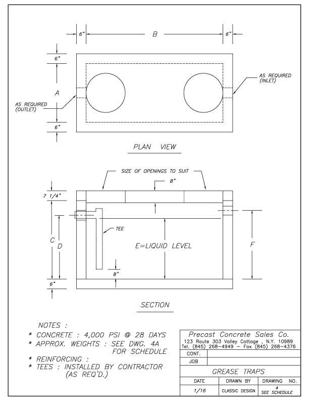
Grease Traps Precast Concrete Sales Company
Detail Grease Trap Design Drawings

grease trap autocad drawing vanlifetshirt

Grease Trap Pit CAD Block And Typical Drawing For Designers
This Article Highlights The Design Principles Needed To Achieve This Goal.
Web In This Blog Post, We Will Discuss The Importance Of Grease Trap Design, Its Key Components, And The Benefits Of Professional Grease Trap Drawings.
Web Design Drawings Serve As A Crucial Tool For Communicating And Visualizing The Specifics Of Your Grease Trap System.
Add Together 100% Of The Largest Flow Rate, 50% Of The Second Largest, And 25% Of Every Other Flow Rate.
Related Post: