Engineering Drawing Views
Engineering Drawing Views - Web understanding the types, principles, and significance of engineering drawing views empowers engineers and designers to communicate design intent effectively, visualize complex geometries accurately, and ensure manufacturability and compliance with industry standards. It also provides a brief introduction to gd&t (geometric dimensioning and tolerancing). Without different views, engineering drawings cannot exist, so understanding how views are used on drawings is a critical. Prepared to provide maximum clarity. We support mechanical and structural engineering professionals. A front view, a top or bottom view, and a left or right view. The height dimension is common to the front and side views. In an isometric drawing, the object’s vertical lines are drawn vertically, and the horizontal lines in the w. In addition, all of the views are aligned. Web the video below covers the fundamentals, including the different types of views, first and third angle projection methods, dimensioning, tolerancing, best practices when creating drawings. Web our engineering drawings, blueprints & plan printing services: Orthographic views can show us an object viewed from each direction. Web views are one of the important parameters in engineering drawings. We'll handle all of your plan printing requirements. Three views are not always necessary; Orthographic views (like top, front, and side views) offer precise dimensions and shapes from different angles. Prepared to provide maximum clarity. Web different views in engineering drawings provide comprehensive visual information about an object. In an isometric drawing, the object’s vertical lines are drawn vertically, and the horizontal lines in the w. Web did you know, views are the building blocks of engineering drawings. Web which views should one choose for a multiview drawing? Web this section will cover the different types of section views, corresponding technical vocabulary, and help you determine which section view would best communicate important aspects of an object or assembly to others. In addition, all of the views are aligned. Web the orthographic view is the core of an. Web did you know, views are the building blocks of engineering drawings. Web the video below covers the fundamentals, including the different types of views, first and third angle projection methods, dimensioning, tolerancing, best practices when creating drawings. Orthographic views (like top, front, and side views) offer precise dimensions and shapes from different angles. Web orthographic views allow us to. Dth and depth planes are shown at 30 degrees to the horizontal. How the views are laid out on a drawing depends on whether 3rd angle or 1st angle projection is being used. An orthographic view or orthographic projection is an approach to depicting a 3d object in 2d. Web this section will cover the different types of section views,. How the views are laid out on a drawing depends on whether 3rd angle or 1st angle projection is being used. A detailed drawing establishes item identification for each part depicted thereon. Without different views, engineering drawings cannot exist, so understanding how views are used on drawings is a critical. We need only as many views as are required to. We need only as many views as are required to describe the object fully. Although in theory the part could be placed in any orientation, the views are usually chosen to coincide with a natural symmetry of the part—for example, the front, right, and top of the car shown above. Galldo group inc is an expert, regularly performing residential and. Three views are not always necessary; Usually, a number of drawings are necessary to completely specify even a simple component. From medical components, or the. Web engineering drawings are one of the most important engineering documents. Web the main elements of the section view are: In addition, all of the views are aligned. Web orthographic views allow us to represent a 3d object in 2d on a drawing. Web an engineering drawing is a type of technical drawing that is used to convey information about an object. Web the orthographic view is the core of an engineering drawing. We support mechanical and structural engineering professionals. Usually, a number of drawings are necessary to completely specify even a simple component. Galldo group inc is an expert, regularly performing residential and commercial surveys in southwest florida state across a diverse spectrum of property types. Dth and depth planes are shown at 30 degrees to the horizontal. Three views are not always necessary; Web different views in engineering. Web different views in engineering drawings provide comprehensive visual information about an object. Three views are not always necessary; Web an engineering drawing is a type of technical drawing that is used to convey information about an object. Learn about the main elements of the engineering drawings. Web a multiview drawing usually consists of three views: An orthographic view or orthographic projection is an approach to depicting a 3d object in 2d. Galldo group inc is an expert, regularly performing residential and commercial surveys in southwest florida state across a diverse spectrum of property types. Web views are one of the important parameters in engineering drawings. The height dimension is common to the front and side. Although in theory the part could be placed in any orientation, the views are usually chosen to coincide with a natural symmetry of the part—for example, the front, right, and top of the car shown above. A front view, a top or bottom view, and a left or right view. Orthographic views can show us an object viewed from each direction. How the views are laid out on a drawing depends on whether 3rd angle or 1st angle projection is being used. We need only as many views as are required to describe the object fully. As a result, a 2d view must convey all information required for part manufacture. Web the video below covers the fundamentals, including the different types of views, first and third angle projection methods, dimensioning, tolerancing, best practices when creating drawings. Web views are one of the important parameters in engineering drawings. Web this section will cover the different types of section views, corresponding technical vocabulary, and help you determine which section view would best communicate important aspects of an object or assembly to others. In an isometric drawing, the object’s vertical lines are drawn vertically, and the horizontal lines in the w. Web hightech & hard work. Web the two main types of views (or “projections”) used in drawings are: Are you looking for a professional firm to help locate the boundary of your property? Sabo designing is an engineering design support. We support mechanical and structural engineering professionals. Galldo group inc is an expert, regularly performing residential and commercial surveys in southwest florida state across a diverse spectrum of property types.
Engineering Drawing Tutorials/Orthographic drawing 2 with Front view
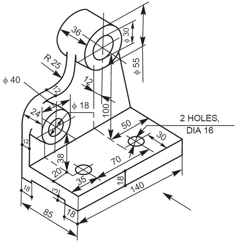
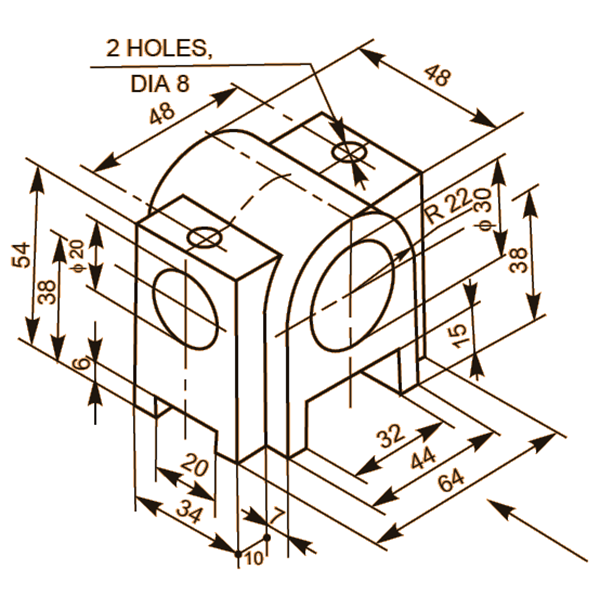
Engineering Drawing at GetDrawings Free download
Sectional View Engineering Drawing Exercises at GetDrawings Free download
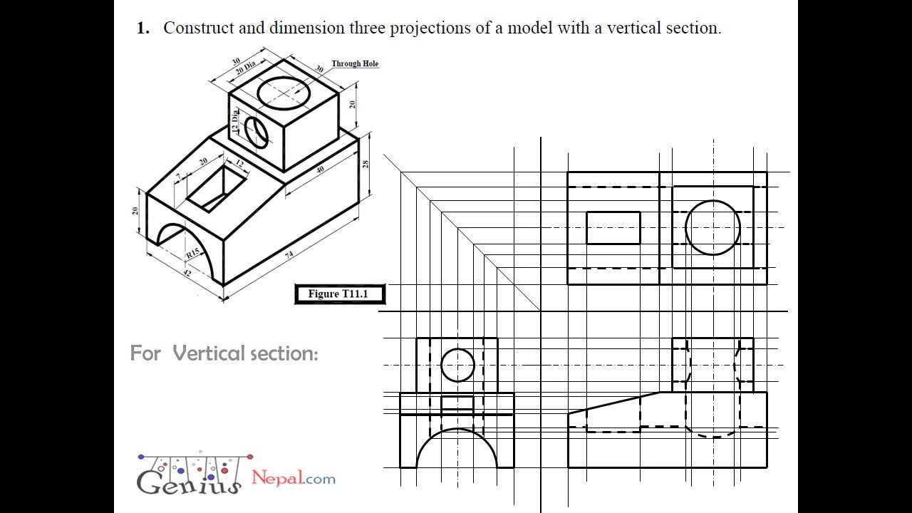
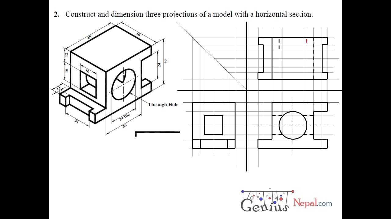
Engineering Drawing Tutorials/Orthographic and sectional views ( T 11.1

Engineering Drawings

Basic Engineering Drawing Projection Knowledge Zone, The Online Support
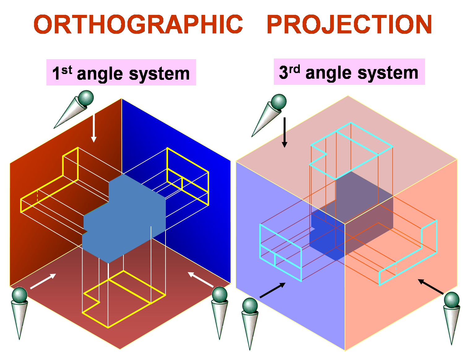
?What do you know about the engineering drawing « Ali's Engineering Design
Projection Definition In Engineering Drawing In an orthographic
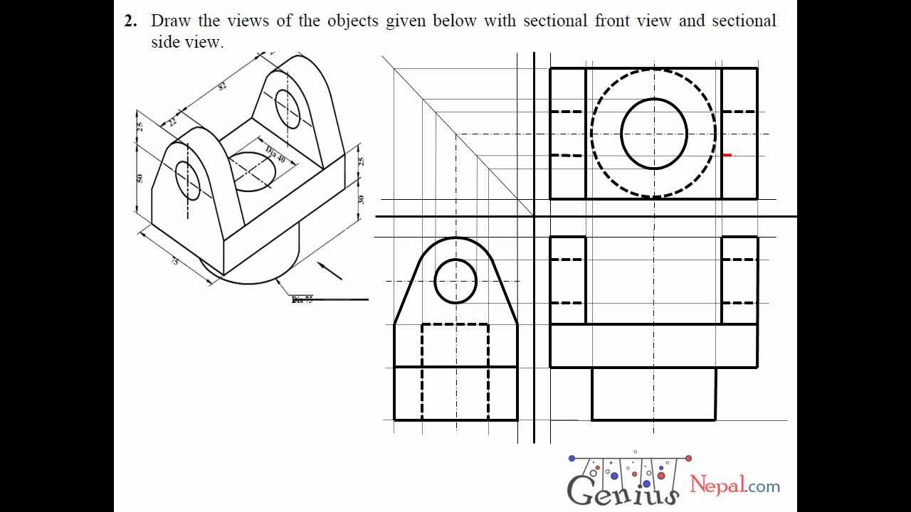
Engineering Drawing Tutorials / Orthographic Drawing with Sectional

Engineering Drawing orthographic sectional view YouTube
Section Line, Section Reference Arrow, Section Reference Letters, Hatch.
Web Different Views In Engineering Drawings Provide Comprehensive Visual Information About An Object.
Web The Orthographic View Is The Core Of An Engineering Drawing.
An Orthographic View Or Orthographic Projection Is An Approach To Depicting A 3D Object In 2D.
Related Post: