Draw The Shear And Moment Diagram
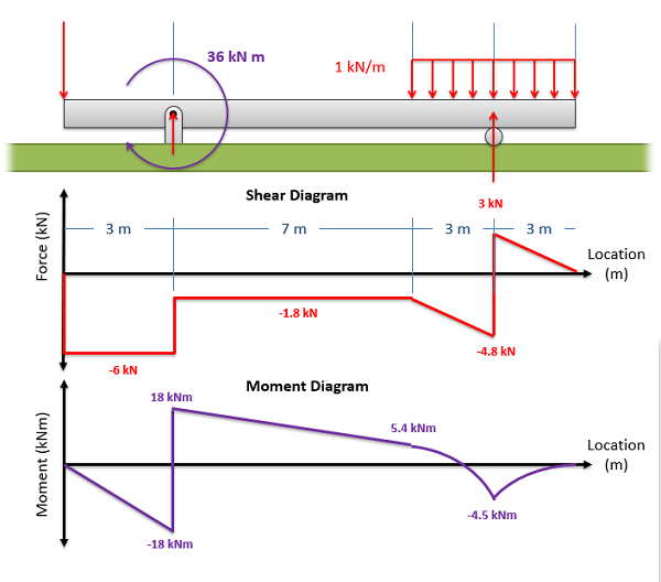
Draw The Shear And Moment Diagram - Web being able to draw shear force diagrams (sfd) and bending moment diagrams (bmd) is a critical skill for any student studying statics, mechanics of materials, or structural engineering. This infographic is an orientation to the concept. Web the previous section presented a method to find the shear and bending moment at a single point, which is useful; Web the maximum positive and negative values on the shear and moment diagrams can be labeled based on the magnitudes of the shear force and bending moment at different locations along the beam. It is sometimes called the graphical method for constructing shear and moment diagrams. The internal forces develop in such a way as to maintain equilibrium. Web therefore the bending moment diagram is: The shear diagram crosses the \(v = 0\) axis at \(x = 5l/8\), and at this point the slope of the moment diagram will have dropped to zero. Web shear (left) and normal (right) internal forces. Lined up below the shear diagram, draw a set of axes. This infographic is an orientation to the concept. Internal forces in beams and frames, libretexts. Web 𝐌𝐲 𝐄𝐧𝐠𝐢𝐧𝐞𝐞𝐫𝐢𝐧𝐠 𝐍𝐨𝐭𝐞𝐛𝐨𝐨𝐤 for notes! Web this video explains how to draw shear force diagram and bending moment diagram with easy steps for a simply supported beam loaded with a concentrated load. To draw the shear and moment diagrams for the given overhang beam, one need to determine the reactions at the supports and analyze the. Lined up below the shear diagram, draw a set of axes. Web shear (left) and normal (right) internal forces. The internal forces develop in such a way as to maintain equilibrium. No matter where the imaginary cut is made along the length of the beam, the effect of the internal forces will always balance the effect of the external forces. Web the previous section presented a method to find the shear and bending moment at a single point, which is useful; Shear force and bending moment diagram example #2: Shear and moment diagrams are graphs which show the internal shear and bending moment plotted along the length of the beam. Web in this video we cover how to draw the shear and moment diagrams for a beam. Web 𝐌𝐲 𝐄𝐧𝐠𝐢𝐧𝐞𝐞𝐫𝐢𝐧𝐠 𝐍𝐨𝐭𝐞𝐛𝐨𝐨𝐤 for notes! Where x x x is the position along. The shear diagram crosses the \(v = 0\) axis at \(x = 5l/8\), and at this point the slope of the moment diagram will have dropped to zero. 10 shear forces and bending enes 220 ©assakkaf moments in beams load, shear force, and bending moment relationships p w1 l b a x1 x2 x3 o w2 figure 19 lecture 13.. The shear diagram crosses the \(v = 0\) axis at \(x = 5l/8\), and at this point the slope of the moment diagram will have dropped to zero. Internal forces in beams and frames, libretexts. They allow us to see where the maximum loads occur so that we can optimize the design to prevent failures and reduce the overall weight. Lined up below the shear diagram, draw a set of axes. To pave its way, this section will deal on how to draw moment diagram by parts and to calculate the moment of such diagrams about a specified axis. The shear diagram crosses the \(v = 0\) axis at \(x = 5l/8\), and at this point the slope of the. Web therefore the bending moment diagram is: But in order to find the shear and moment at every point in the object you will need a more powerful approach. The internal forces develop in such a way as to maintain equilibrium. Shear force and bending moment diagrams are analytical tools used in conjunction with structural analysis to help perform structural. Web beamguru.com is a online calculator that generates bending moment diagrams (bmd) and shear force diagrams (sfd), axial force diagrams (afd) for any statically determinate (most simply supported and cantilever beams) and statically indeterminate beams, frames and trusses.the calculator is fully customisable to suit most beams,. What we really want is an equation that tells us the value of the. To draw the shear and moment diagrams for the given overhang beam, one need to determine the reactions at the supports and analyze the. Shear and moment diagrams are graphs which show the internal shear and bending moment plotted along the length of the beam. Web the previous section presented a method to find the shear and bending moment at. The moment diagram is now parabolic, always being one order higher than the shear diagram. Web below is a simple example of what shear and moment diagrams look like, afterwards, the relation between the load on the beam and the diagrams will be discussed. We go through breaking a beam into segments, and then we learn about the relatio. Shear. To draw the shear and moment diagrams for the given overhang beam, one need to determine the reactions at the supports and analyze the. Assume that the beam is cut at point c a distance of x from he left support and the portion of the beam to the right of c be removed. Web in this video we cover. Web this video explains how to draw shear force diagram and bending moment diagram with easy steps for a simply supported beam loaded with a concentrated load. Here's an example of a cut made just after the first support (which has an upward force. Shear and moment diagrams (graphical) (5.3) slide no. The portion removed must then be. Example 2. Assume that the beam is cut at point c a distance of x from he left support and the portion of the beam to the right of c be removed. Web the maximum positive and negative values on the shear and moment diagrams can be labeled based on the magnitudes of the shear force and bending moment at different locations along the beam. If the shear diagram is a parabola, the moment diagram will be a cubic. The portion removed must then be. Shear and moment diagrams are graphs which show the internal shear and bending moment plotted along the length of the beam. Web 6.2 shear/moment diagrams 6.2.1 what are shear/moment diagrams? What we really want is an equation that tells us the value of the shear force and bending moment as a function of x x x. Web below is a simple example of what shear and moment diagrams look like, afterwards, the relation between the load on the beam and the diagrams will be discussed. The shear diagram crosses the \(v = 0\) axis at \(x = 5l/8\), and at this point the slope of the moment diagram will have dropped to zero. Lined up below the shear diagram, draw a set of axes. The moment diagram is now parabolic, always being one order higher than the shear diagram. Web but to draw a shear force and bending moment diagram, we need to know how these values change across the structure. Shear and moment diagrams (graphical) (5.3) slide no. In general the process goes like this:1) calcul. This is a very useful skill to be good at for statics and mechanics of materials. We go through breaking a beam into segments, and then we learn about the relatio.
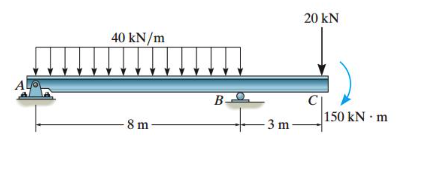
Solved Draw the shear and moment diagrams for the beam

Learn How To Draw Shear Force And Bending Moment Diagrams Engineering
How To Draw Shear Force And Bending Moment Diagram For Frames

Draw Shear And Moment Body Diagrams
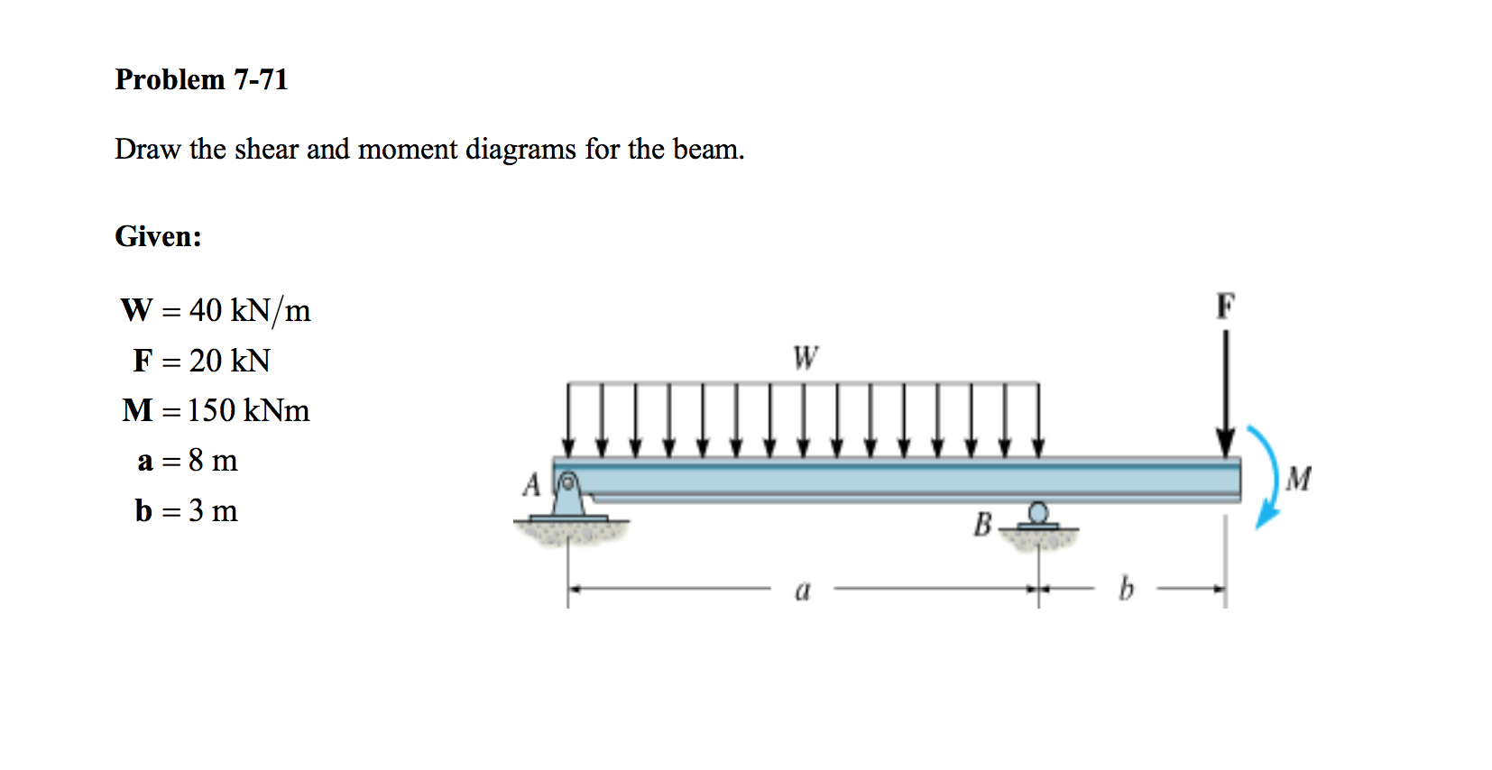
Solved Draw the shear and moment diagrams for the beam.

Draw The Shear Diagram For Beam The Best Picture Of Beam
Mechanics Map Shear and Moment Diagrams

Shear and moment diagrams geekloki
Solved Draw the shear and moment diagrams for the beam using

Solved Draw the shear and moment diagrams for the beam, and
Web Learn To Draw Shear Force And Moment Diagrams Using 2 Methods, Step By Step.
This Infographic Is An Orientation To The Concept.
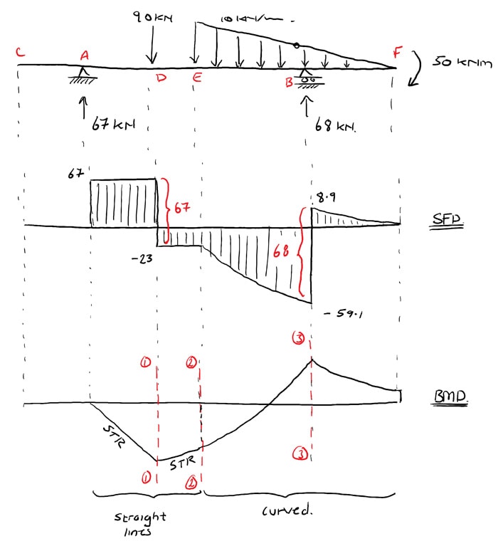
Example 2 Draw The Shear Force And Bending Moment Diagrams For The Beam Show Below:
Shear Force And Bending Moment Diagrams Are Analytical Tools Used In Conjunction With Structural Analysis To Help Perform Structural Design By Determining The Value Of Shear Forces And Bending Moments At A Given Point Of A Structural Element.
Related Post: